citation: @online{trigger,
collaboration = "LHCb collaboration",
title = "Trigger Schemes",
urldate = "{your date}" }
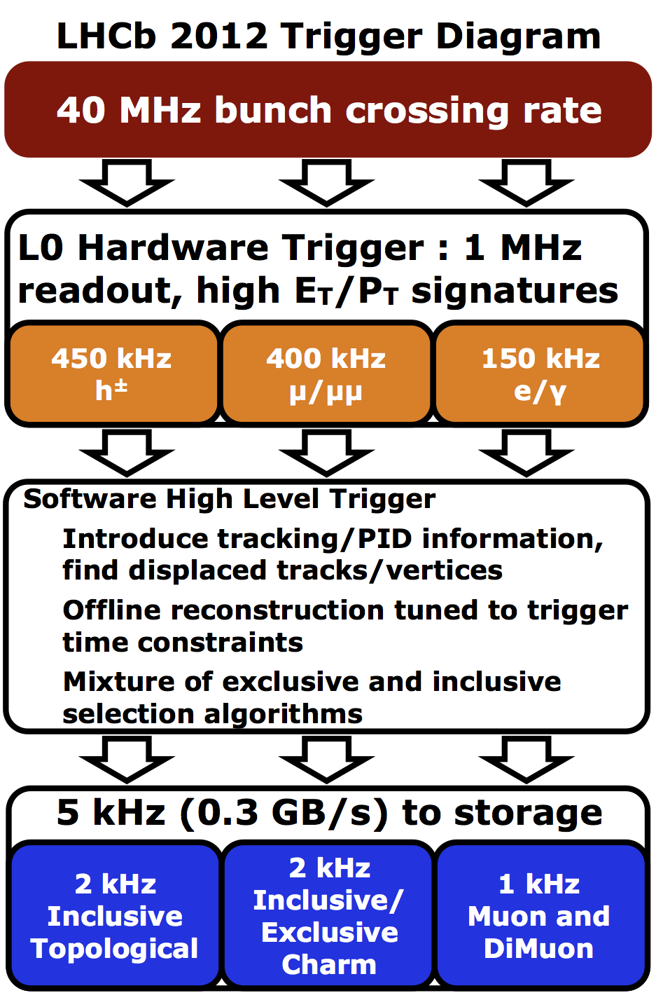
RUN I |
Run I Alg Details |
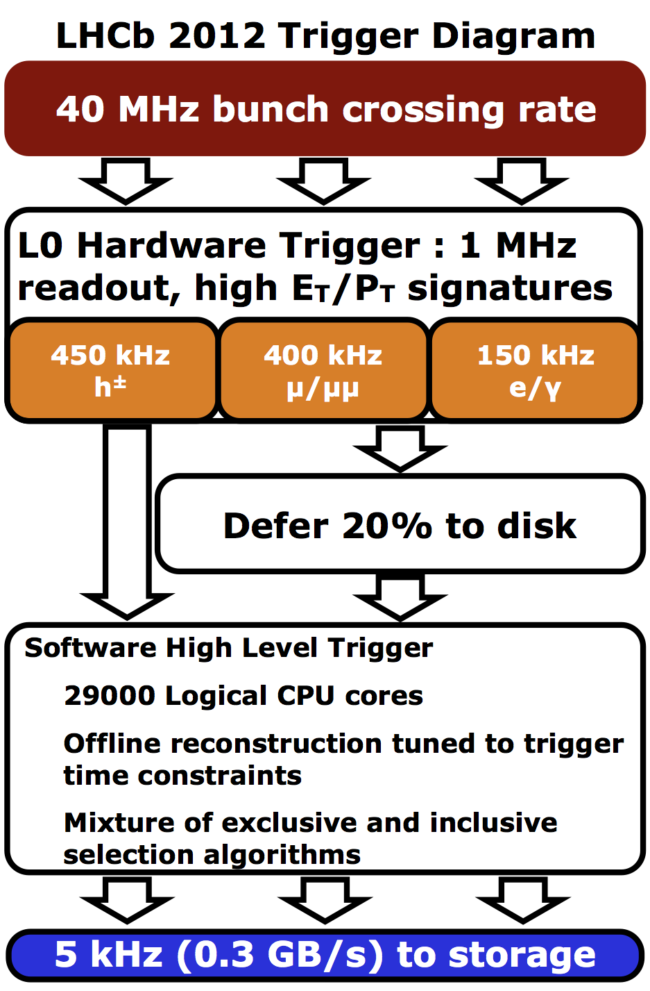
Run I Deferral |
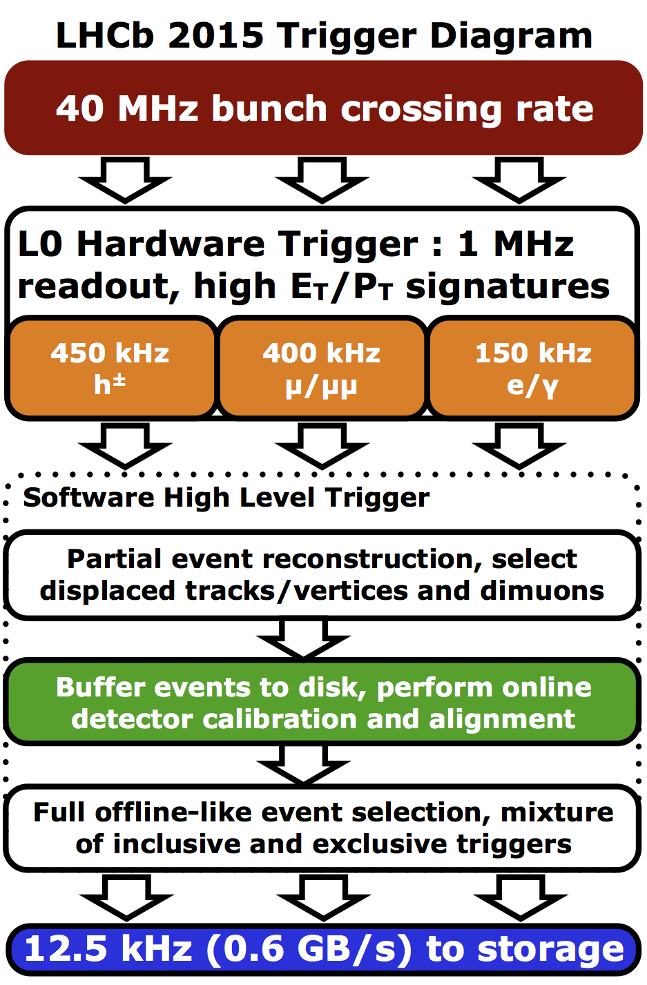
Run II |
Run III |
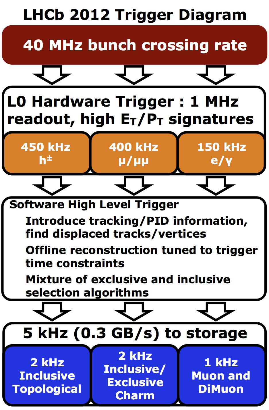
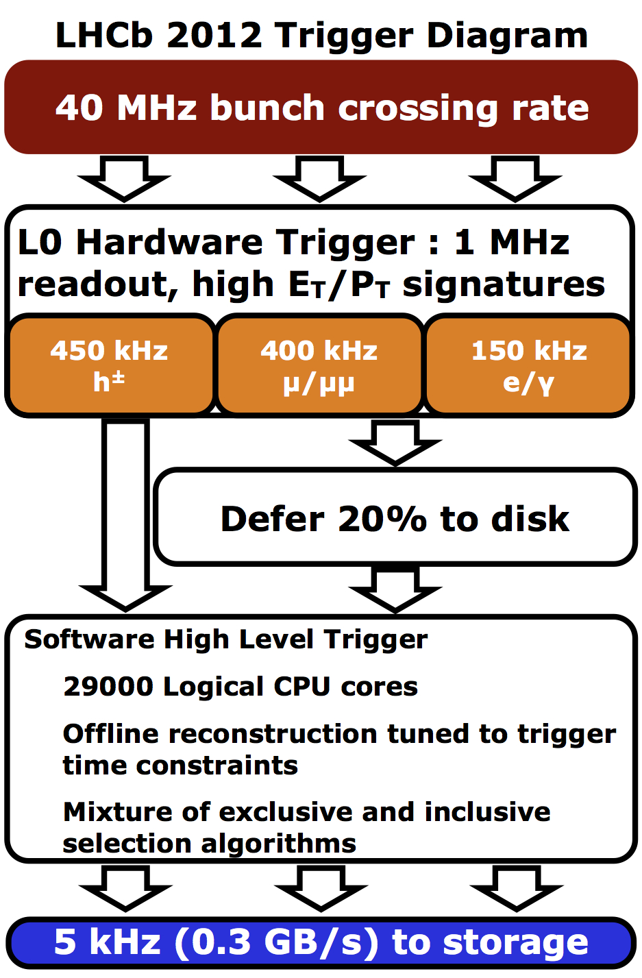
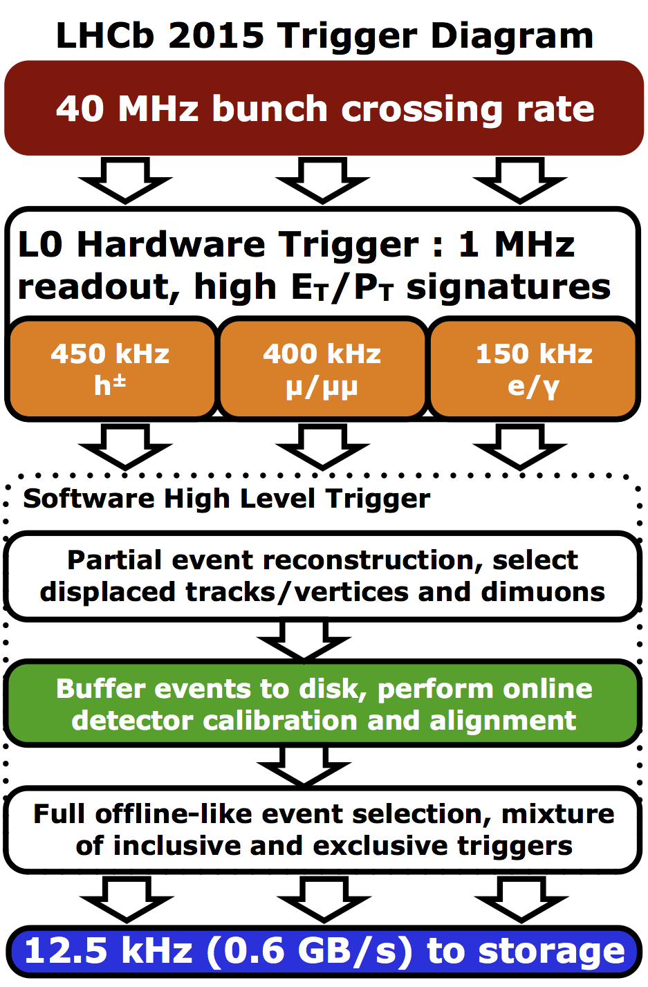
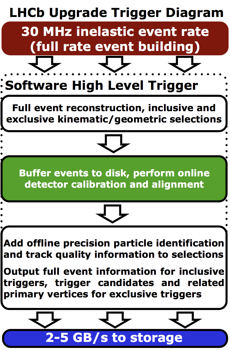
| The Run I trigger layout without the details of the algorithms used in the HLT or the deferral | Also contains some information about the different HLT algorithms | Illustrates the way the deferral fit into the trigger dataflow | The Run II trigger scheme illustrating the central place of the detector alignment and calibration. | The upgrade diagram illustrating the continuing use of real time alignment and calibration, as well as giving some details on how events will be split into full/turbo streams. |
 |
 |
 |
 |
 |
| (jpg, pdf, png) | (jpg, pdf, png) | (jpg, pdf, png) | (jpg, pdf, png) | (jpg,pdf,png) |
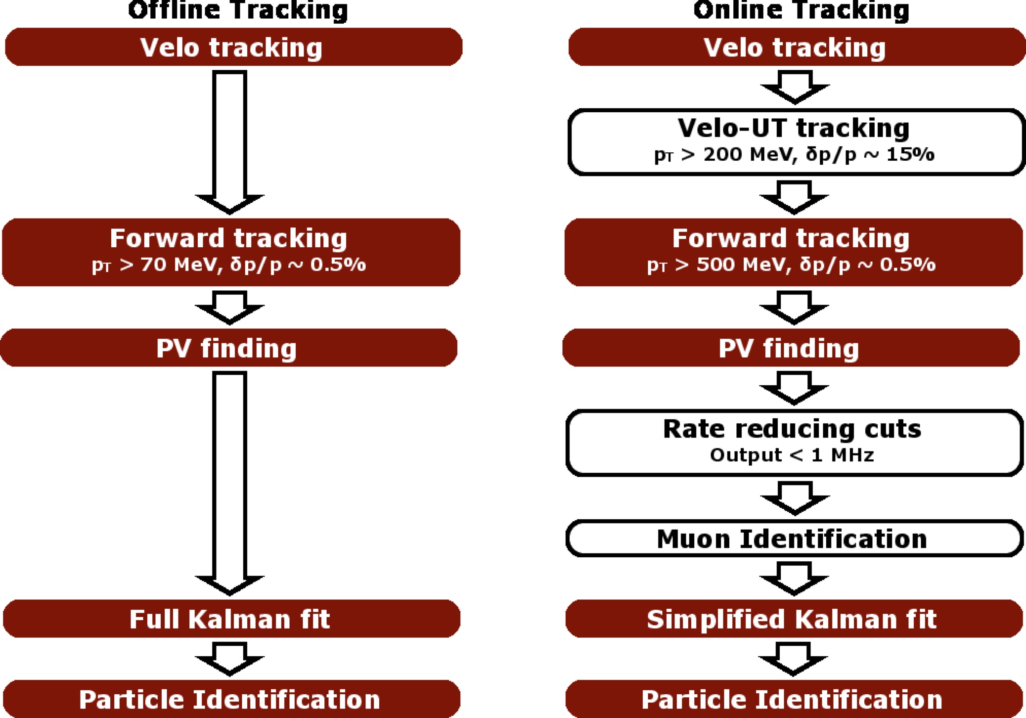
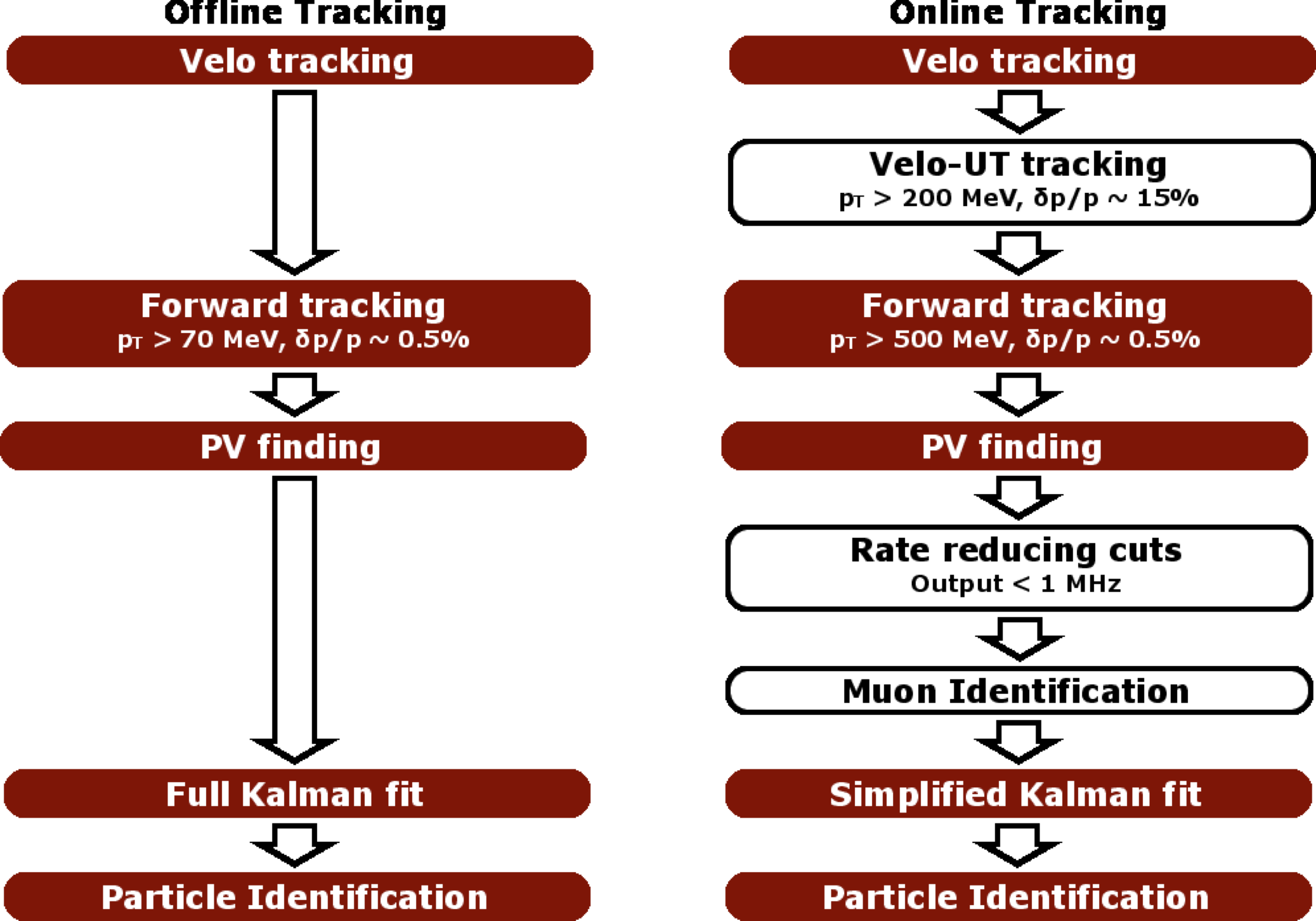
Upgrade HLT Reconstruction |
|
|
| (jpg,pdf,png) |
Note that for all Run I and Run II diagrams, the input rate is 40 MHz. This is because for the current detector you can only read it out at 1 MHz so what matters is the overall bunch crossing rate which has to be reduced by the hardware trigger. For the upgrade detector, you can read everything out so what matters is the non-empty bunch crossing rate because this is what has to be reduced by the HLT. Therefore the upgrade diagram has the input rate at 30 MHz.
If you have questions or comments
regarding these trigger schemes, please
contact lhcb-hlt-piquet@cern.ch .